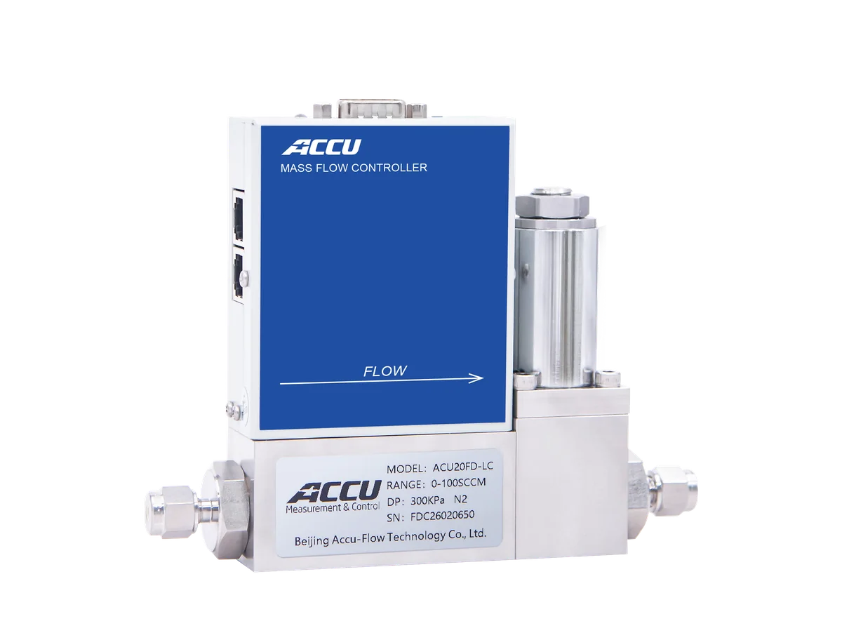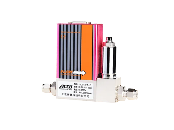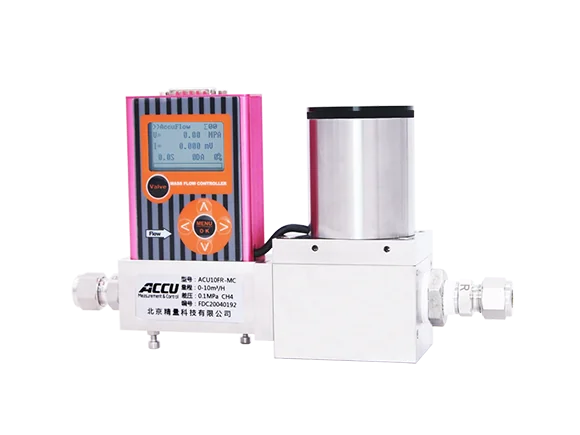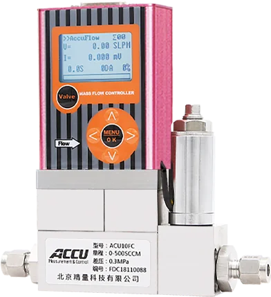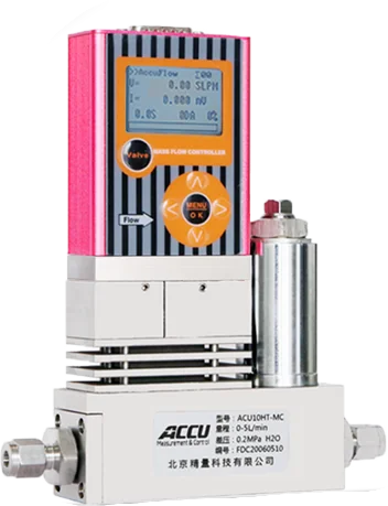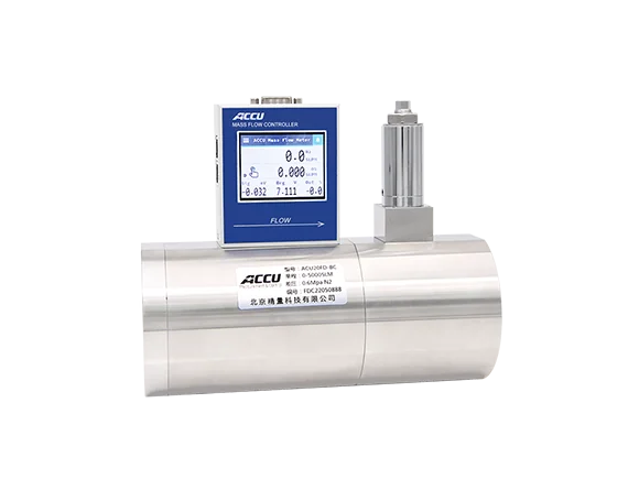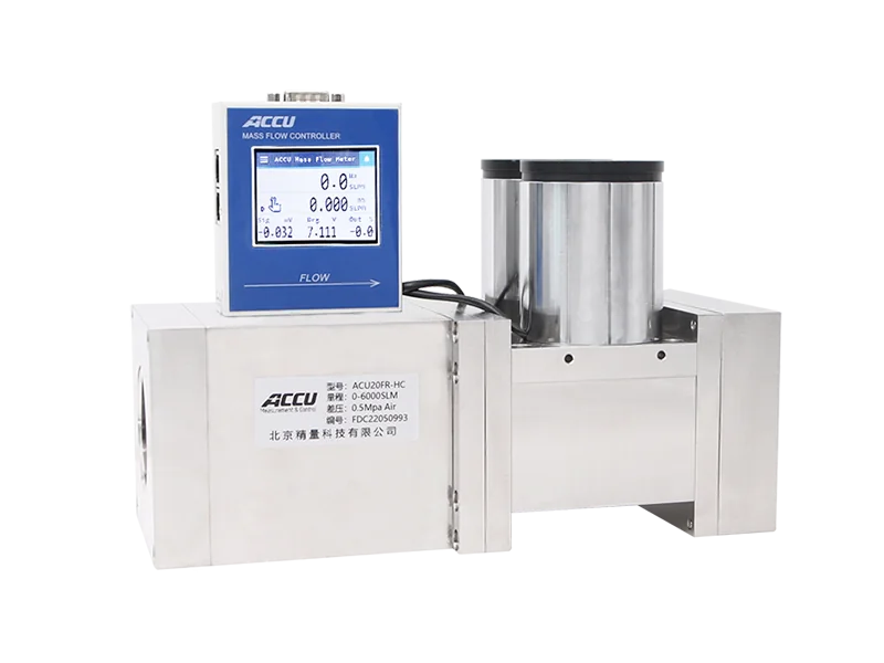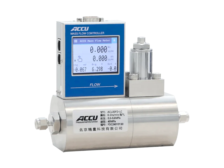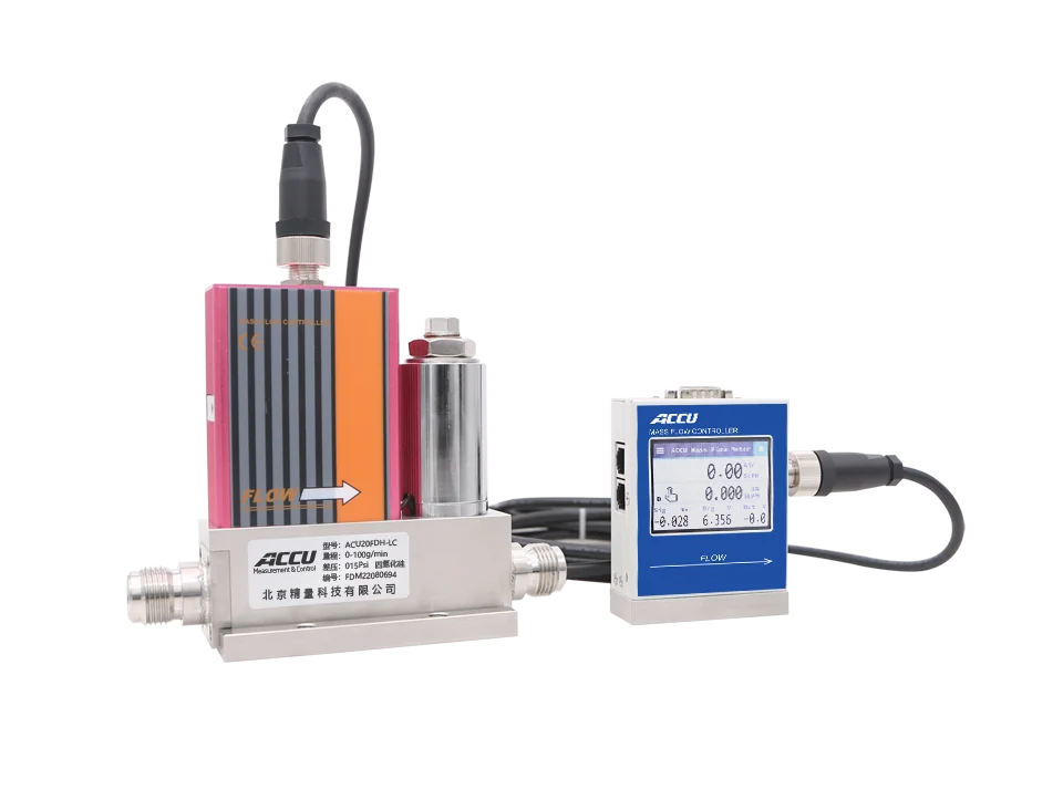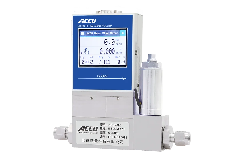
ACU10FD Series
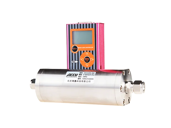
The ACU10FD digital mass flow controller comprises a mass flow sensor, a laminar flow element, a flow‑control regulating valve, and an amplification control circuit. It features digital signal input and output, short warm‑up time, low zero drift, and high reliability.
Range: 0-3000SLM
Overview
Applications
Specifications
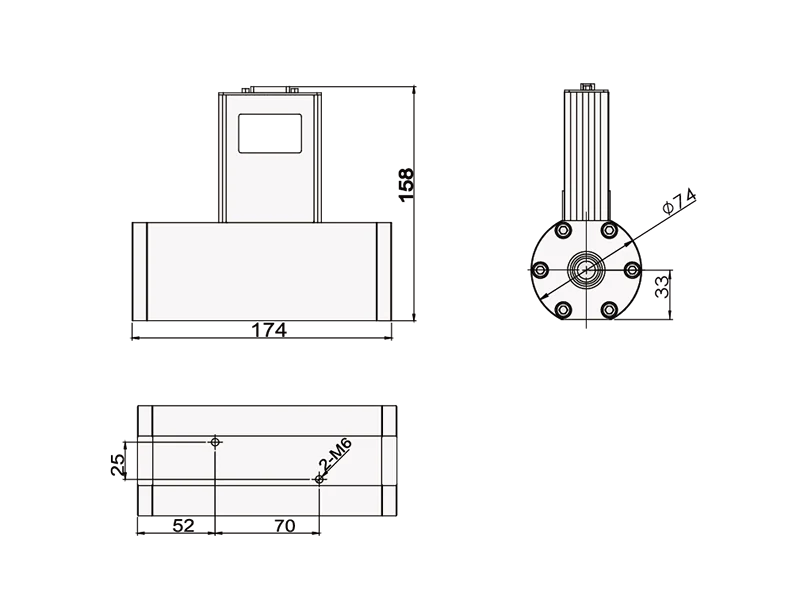
Dimensions
Software
◆ Thermal principle, fast response, high accuracy
◆ Tubular shunt, less prone to blockage
◆ Suitable for various low-pressure and high-pressure pipelines
◆ Short warm-up time, minimal zero drift, and high reliability
◆ Digital inputs/outputs can use secondary instruments or flow computers to control and display flow rates.
The ACU10FD mass flow controller consists of a mass flow sensor, a laminar‑flow element, a flow‑control regulating valve, and an amplification‑and‑control circuit. It operates on the principle of thermal conduction—where heat transfer by the flowing fluid alters the temperature distribution along the wall of a measurement capillary.
The ACU10FD mass flow controller measures gas mass flow using the capillary‑based differential‑temperature calorimetric principle, ensuring independence from temperature and pressure variations. It amplifies the flow signal detected by the sensor, compares it with a setpoint voltage, and uses the resulting error to drive a control valve, thereby maintaining closed‑loop regulation of the flow rate through the channel to match the desired value.
| Glass industry | Solar energy | Atmospheric monitoring | Industrial manufacturing | Petroleum and Petrochemicals |
| Coal Metallurgy | Gas production and gas distribution | Environmental protection | Various instrumental analyses | |
| Series | ACU10FD | |||||
| Model number | LC | LM | MC | MM | British Columbia | BM |
| Measurement range | 0–(2, 5, 10…1000) SCCM, 0–(1, 5, 10…30) SLM | 0-(30,40,50...300)SLM | 0-(300,400,500...3000)SLM | |||
| Accuracy | ±1.0%F.S | |||||
| Linear | ±0.5%F.S | |||||
| Repeatability | ±0.2%F.S | |||||
| Working differential pressure | 0.1–0.5 MPa (to be specified at the time of order) | |||||
| Range ratio | 50:1 | 100:1 | 50:1 | 100:1 | 50:1 | 100:1 |
| Response time | <0.8s | |||||
| Analog quantity | 0–5 V, 4–20 mA | |||||
| Digital quantity | RS232/485, MODBUS protocol | |||||
| Power supply | ±15 VDC, 24 VDC | |||||
| Operating temperature | 0–50°C | |||||
| Working pressure drop | <0.01 MPa | |||||
| Maximum withstand voltage | 3 MPa / 10 MPa (to be specified at the time of order) | |||||
| Electrical connection | DB15 port | |||||
| Leak rate | 1×10⁻⁹ Pa·m³/s | |||||
| Temperature coefficient | ±0.025%F.S/℃ | |||||
| Valve | Valve normally closed | / | Valve normally closed | / | Valve normally closed | / |
| Base material | Stainless steel | |||||
| Sealing material | Fluororubber, nitrile rubber, EPDM, perfluoroether | |||||
| Body thread | G3/8 internal thread | G1/2 internal thread | ||||
| Joint | Ferrules, ferrule fittings, quick-connect couplings, VCR fittings, flanges, and more | |||||
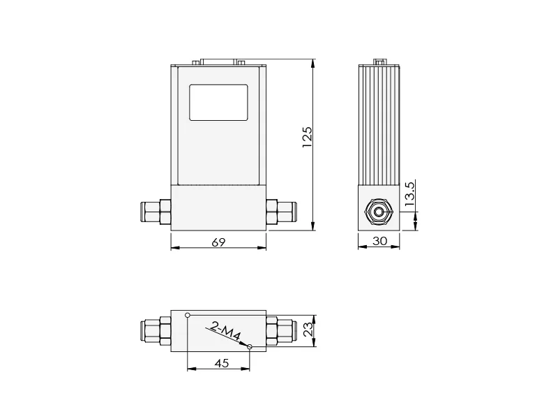
ACU10FD-LC Dimensional Drawing
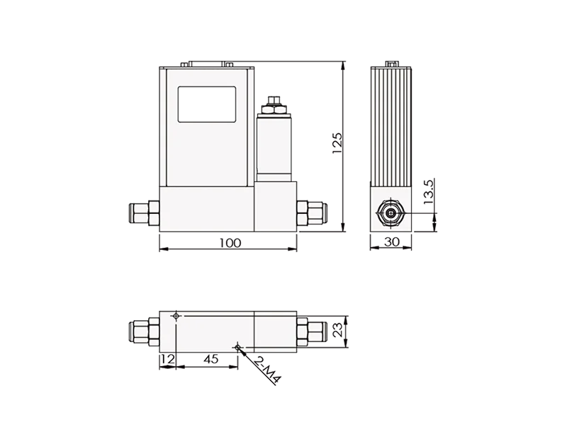
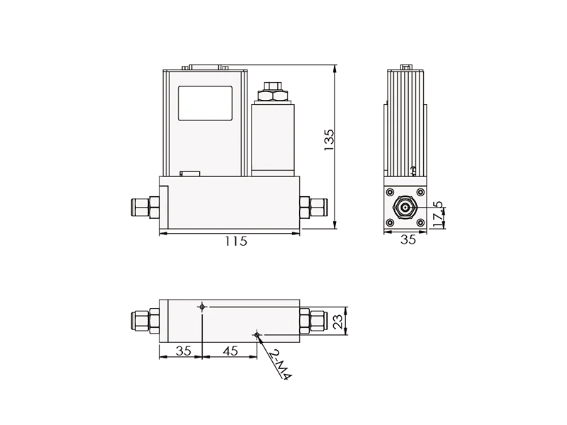
ACU10FD-LM Dimensional Drawing
ACU10FD-MC Dimensional Drawing
ACU10FD-MM Dimensional Drawing
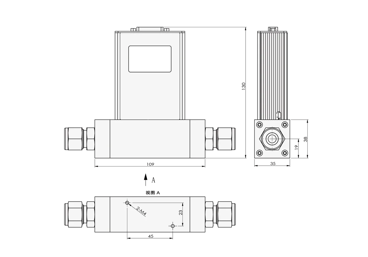
ACU10FD-BC Dimensional Drawing
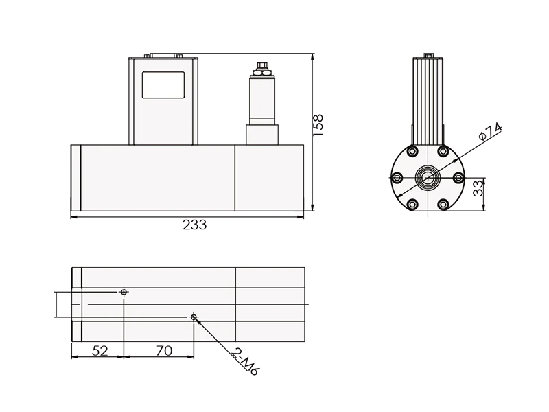
ACU10FD-BM Dimensional Drawing
Mass Flow Measurement and Control System V5.0